Optimisation of self-generated PV energy with a car battery and intelligent charging management
Step by step.
Step by step.
In order to optimally use the self-generated PV energy, it is important to use the energy surplus flexibly, especially during times of high PV yield. One way to absorb the surplus is to use a car battery as a flexible energy storage system. However, there are some important aspects to consider, especially with regard to charging the vehicle.
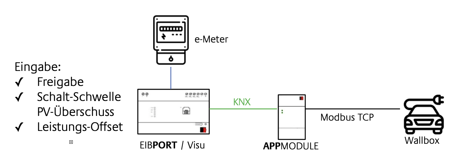
To achieve this goal, a logic group is used in the EIBPORT for control. Communication with a charging station (wallbox) takes place via the APP MODULE in conjunction with a corresponding Smart Home app. Direct communication between the control unit and the wallbox enables dynamic charging that takes the PV energy yield into account.
Implementation of intelligent charging management with sample configuration
To enable you to create an individual solution, an example is described below that can serve as a basis. The configuration is carried out in the logic editor of the EIBPORT, while the interface to the charging station or wallbox is set via the APP MODULE. Various Smart-Home APPs are available for selection here, both manufacturer-specific and the generic Modbus-TCP-Connect Smart-Home APP.
Two outputs are available for specifying the charging power:
This example does not yet take into account: The monitoring of the battery level, and the automatic stopping of the charging process when the vehicle is fully charged.
The charging of the car battery is carried out with variable power. Depending on the available values of the wallbox, the entire status of the car battery can be monitored in addition to the power monitoring for charge control and, if necessary, other functions such as the charging time or the battery level can be used for control.

About the functioning of the logic group
The measured values of the performance recording are stored in a cache every minute and forwarded from there to a statistics element. Ten values are recorded in this element and the mean value is calculated, which is then sent every ten minutes. The averaging and the 10-minute interval are used to smooth the measured value for the switching threshold and the power specification for charging.
The user sets an upper and lower switching threshold, whereby the lower switching threshold can be provided with an offset to prevent premature switching back. Otherwise, the value "0" is entered. This ensures that charging is not aborted too early, even if the PV surplus range is left. During charging, the measured power value must be corrected by the power value of the wallbox so that the switching thresholds are not influenced.
The correction is based on the feedback from the wallbox and occurs even if the power specification for charging is higher. Enabling "ON" activates the logic group, while enabling "OFF" stops the logic group and sets the switching command to the wallbox to "OFF". An integrated start value is required to ensure that the logic group has a defined output value.
Input values (settings of the user):
Initial values: