Variable use of mini-PV energy surplus
Step by step.
Step by step.
After investing in a PV system, the question arises as to how the self-generated energy can be optimally used. Often, mini PV systems generate more energy than the basic consumption of the connected appliances requires. The purchase of an energy storage unit is still quite expensive, and partial feeding into the grid is not economically viable.
Use of the energy surplus for consumers: Beverage cooler
In this case, the surplus electricity is used to supply a beverage cooler. It should be noted that the cooler does not require continuous energy. More energy is needed to lower the temperature than to maintain the temperature level. Since the energy surplus is also not constant, the cooler switches on and off irregularly. Without an energy buffer, the contents of the cooler would heat up to ambient temperature overnight while being pleasantly cooled during the day. Similar scenarios are also possible with other devices such as air purifiers, dehumidifiers, etc.
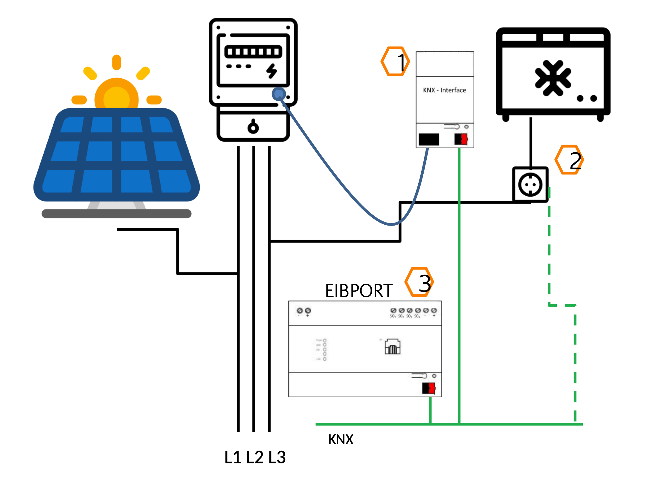
Recording of the total consumption in the household with opto-coupler/KNX interface or radio solutions
The current total consumption of the household can be read in quite easily via an opto-coupler/KNX interface from the house connection meter. Alternatively, there are various radio solutions such as Shelly EM, Tasmota or other radio protocols. To find corresponding proposed solutions with prepared logic groups, use the search function or the following logic group: Energy meter Opto-coupler Wifi with value adjustment
Selection of control options
Shelly switch actuators or Shelly intermediate plugs can be used for switching the cooler. A Shelly switch actuator allows the chiller to be switched, the current power to be detected and the chiller temperature to be integrated into the KNX system. This allows the chiller temperature to be displayed and further control options to be added. It is important to note that control is not continuous when there is a surplus of energy and can lead to temperature fluctuations. However, these fluctuations should not have a negative impact on the shelf life of the products in the cooler.
The measured values of the house connection meter are already available and the beverage cooler is also integrated into the KNX system with the required functions. In order to realise the control in the event of an energy surplus, the logic group Balcony PV - surplus energy be used.
To do this, the LOGIC EDITOR is called in the EIBPORT and the logic group can be imported. This logic group was created in order to import a static value "Additional service W" for the energy surplus control. This input value is now used as the input value for the consumption power of the cooler.

The following 2 input values must be taken into account:
The function elements used in the example are:
The two initial values are: